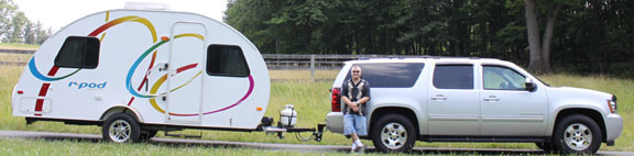
12 volt power socket installed in 177

|
|
Post Reply 
|
Page 123 6> |
| Author |
 Printable Version Printable Version Google Google Delicious Delicious Digg Digg StumbleUpon StumbleUpon Windows Live Windows Live Yahoo Bookmarks Yahoo Bookmarks reddit reddit Facebook Facebook MySpace MySpace Newsvine Newsvine Furl Furl Topic Search Topic Search  Topic Options Topic Options
|
jj 
Groupie 
Joined: 04 Dec 2013 Location: ca Online Status: Offline Posts: 42 |
 Topic: 12 volt power socket installed in 177 Topic: 12 volt power socket installed in 177Posted: 07 Dec 2013 at 7:38pm |
|
12 volt DC socket for r-pod 177   Disconnect 120 volt power cord from r-pod to house if connected. Disconnect 12 volt deep cycle battery by removing negative cable. Remove wooden top from dinette seat  Open front cover (access door) converter. WFCO converter.
")
Turn off all the breakers inside the panel, extra precaution. Breakers are in the middle of the panel to right of the paper with the word “MAIN”. (see picture above) Remove front cover from the panel by removing screws.   Panel shown with breakers and 12 volt automotive fuses on the right side on green circuit board and with front panel removed. Look for empty 12 volt connection screw on right side of the panel (green circuit board) to the right of the automotive fuses. This particular panel has 2 empty connection screws at the bottom of the 12 volt circuit board. Use one of those connection screws. 12 volt power sockets, you can choose the following: 12 volt dash sockets (black) drill 1 1/8 hole in the side panel of the bench seat. 12 volt DC power socket with metal cover plate. Drill hole in the side of bench seat (make sure there is space) and install the 12 volt power socket, secure by tightening large nut on back of socket against backside of the panel. Secure plate with screws. Pop out 12 volt DC circuit board from the panel housing to get access to the back of the circuit board to guide wire inside the converter housing to the front of the circuit board, or guide wire with board in place. Use 14 or 12 gauge wire 1 red and 1 black. Red wire will be the power source wire connected to the 12 volt DC circuit board connection screw. Black wire will be the ground wire connected to the 12 volt DC ground bus bar behind the WFCO power panel housing. It is screwed to the floor of the trailer. (metal strip with holes on side and screws on top) Top view back side of power converter panel housing. 
12 volt DC Ground bus bar is in this picture right below the roll off white wire Top view with ground wires connected to ground bar behind the converter panel housing, ground bus bar screwed to the floor, connect ground wire from the 12 volt power socket to the ground bus bar. Wiring diagram below, use 2 crimp-on vinyl female connectors for the back of 12 volt DC power socket. Connect one to the red wire and the other to the black wire and connect to back of 12 volt DC power socket. Red to the power side of the socket and black to the ground side of the socket. Use crimp-on female connectors, 12 guage sample shown Automotive fuse, 10 amp sample fuse shown  After installation is finished, install automotive fuse in the slot next to the connection screw dedicated to power the 12 volt DC power socket. |
|
 |
|
|
techntrek
Admin Group - pHp 
Joined: 29 Jul 2009 Location: MD Online Status: Offline Posts: 9059 |
Posted: 08 Dec 2013 at 3:42pm |
|
Nice write-up. I took the last pic out of your post and replaced it with a link to the pic, for some reason that pic was completely messing up the page layout.
|
|
|
|
|
Jdub
Groupie
Joined: 17 Mar 2013 Online Status: Offline Posts: 94 |
Posted: 08 Dec 2013 at 3:58pm |
|
Is the ground wire the same as the big white wire on the top left of the green fuse panel?
|
|
|
|
|
jj
Groupie
Joined: 04 Dec 2013 Location: ca Online Status: Offline Posts: 42 |
Posted: 08 Dec 2013 at 7:39pm |
|
the big white wire on the top left of the green fuse circuit board is the negative cable from the converter which is located in the bottom of the panel housing.
|
|
|
|
|
jj
Groupie
Joined: 04 Dec 2013 Location: ca Online Status: Offline Posts: 42 |
Posted: 08 Dec 2013 at 7:43pm |
|
|
|
|
|
|
Jdub
Groupie
Joined: 17 Mar 2013 Online Status: Offline Posts: 94 |
Posted: 08 Dec 2013 at 7:58pm |
So can't you also ground a negative from the 12v to it? |
|
|
|
|
Sleepless
Senior Member 
Joined: 07 Jun 2013 Location: Titusville, FL Online Status: Offline Posts: 556 |
Posted: 08 Dec 2013 at 8:43pm |
|
A ground is a ground.
|
|
|
2014 R-Pod 178 (OUR POD)
2009 Chevrolet Avalanche |
|
|
|
|
jj
Groupie
Joined: 04 Dec 2013 Location: ca Online Status: Offline Posts: 42 |
Posted: 08 Dec 2013 at 8:44pm |
|
Use the ground bus bar behind the converter panel housing for propper connection.
in the panel you would normaly see two big white wires connected to that terminal top left of the green fuse circuit board. one coming from the converter and the other going to the ground bus bar behind the converter.
|
|
|
|
|
Jdub
Groupie
Joined: 17 Mar 2013 Online Status: Offline Posts: 94 |
Posted: 08 Dec 2013 at 10:16pm |
Ok, but I already put my 12v with the ground going to the ground wire in the panel as I described above.....no reason to re-wire I would assume?
|
|
|
|
|
furpod
Moderator Group - pHp 
Joined: 25 Jul 2011 Location: Central KY Online Status: Offline Posts: 6128 |
Posted: 08 Dec 2013 at 11:12pm |
|
Would be nice if you are going to use someone else's pictures.. that you at least ask first if you are posting them as YOUR mod..

|
|
|
|
|
Post Reply
|
Page 123 6> |
| Forum Jump | Forum Permissions You cannot post new topics in this forum You cannot reply to topics in this forum You cannot delete your posts in this forum You cannot edit your posts in this forum You cannot create polls in this forum You cannot vote in polls in this forum |