
|
Moving Lithium batteries to under bench seat |
Post Reply 
|
Page <12 |
| Author |
 Printable Version Printable Version Google Google Delicious Delicious Digg Digg StumbleUpon StumbleUpon Windows Live Windows Live Yahoo Bookmarks Yahoo Bookmarks reddit reddit Facebook Facebook MySpace MySpace Newsvine Newsvine Furl Furl Topic Search Topic Search  Topic Options Topic Options
|
Ibcj 
Newbie 

Joined: 01 Sep 2021 Location: CA Online Status: Offline Posts: 5 |
 Post Options Post Options
 Quote Reply Quote Reply
 Topic: Moving Lithium batteries to under bench seat Topic: Moving Lithium batteries to under bench seatPosted: 31 May 2022 at 1:13am |
|
Appreciate your thoughts offgrid; learning through your experiences is saving me a bunch of mistakes already!
So I tore apart the front under-belly access panel as well as the WFCO power distribution unit today and started mapping out the wires, circuit breakers, and tracing out as much as I could see. I feel much more comfortable about what it will take to put the LiFePO4 batteries into the TT now. Coming from the battery there were two sets of leads on each post. The "primary" set was 8ga, and one ran directly to a chassis ground, the other into a couple short stops just inside the trailer floor under the front access panel. The other two leads are 10ga and run along the frame with the rest of the wiring after also going through a short stop in the access panel. I see matching 10ga red & black leads come up from the floor behind the WFCO and run up the wall next to the pantry. Best I can guess, these are the leads for the solar hookups on the roof. Any other ideas/suggestions for what these could be? I ran out of daylight, but will continuity test them tomorrow. On the 193, there's a lovely compartment under the furnace that would be kind of be perfect for the Li battery. I'm pretty sure that it's the solar roof wiring (from above) that runs through there, it is next to the WFCO, and is otherwise unused space. Unfortunately the ridiculous huge Renogy 200Ah battery I bought won't fit unless I move around some PEX supply lines, and that juice just doesn't feel worth the squeeze. So best option I can see is to put the Li battery and supporting equipment under the front couch, in the LH corner, which is where the water pump is located (easy access to the underbelly). 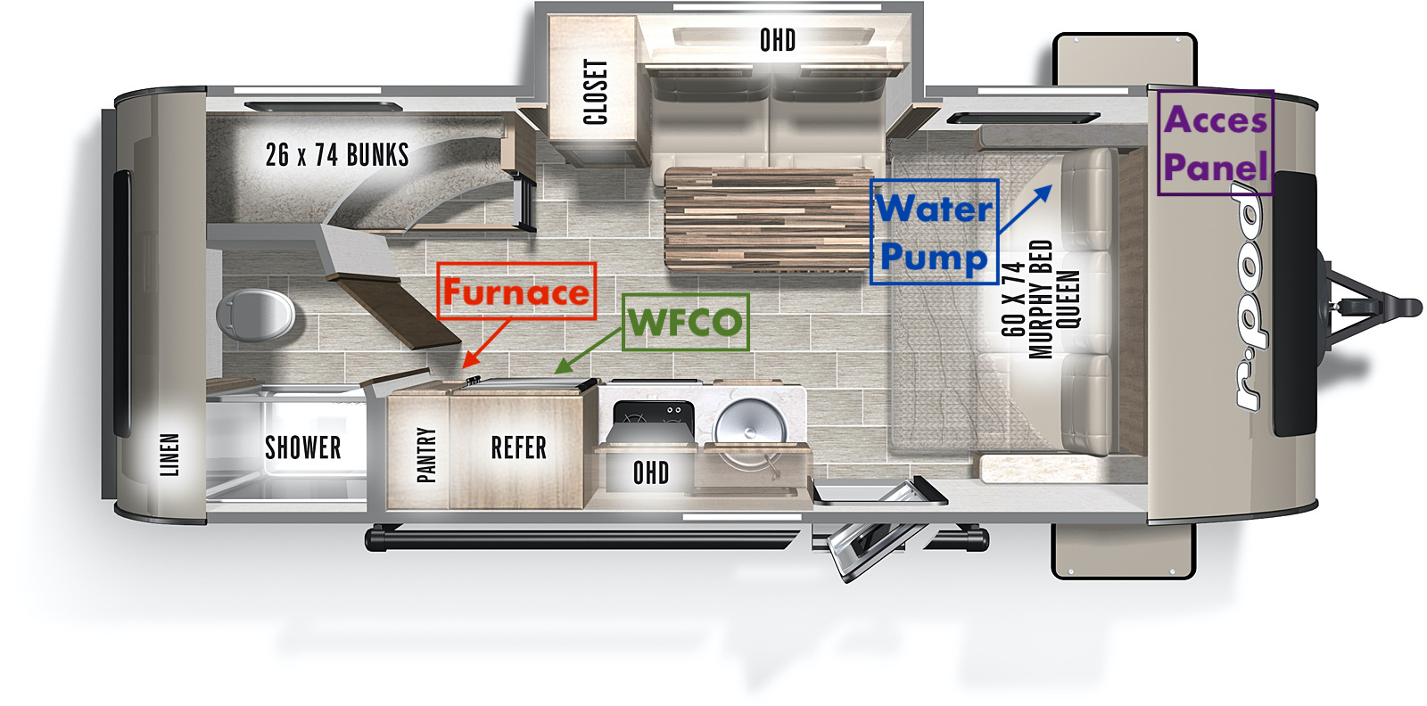 I haven't been able to get anyone from Renogy on the phone, and I can find any recommendations from them on what charge controller to use. So my thought is go with a 60A Progressive Dynamics Li Charge Controller (PD9160ALV) which should only pull ~9A on 110, so that gives me plenty of safety margin on a 15A/14ga circuit (the 80A version notes it needs a 20A circuit and would pull ~11.8A, so cutting it too close I suspect). I'm going to call the PD guys tomorrow. The Renogy looks to have a decent (I think?) integrated BMS, so I'm guessing it will be safe inside the TT. And from what I've read, the LiFePO4's are way less likely to ignite than other Li options - but I'm green on this so looking for comments! I'm sorry that the WFCO's fried your batteries. That's a bummer. My WFCO integrated converter looks easy to disconnect, so I'll mount the DC-to-DC converter and the PD Charge Controller next to the battery under the front couch. I think the trickiest part will be pulling a "home run" of Romex from the WFCO panel to the charge controller under the bed. I'm going to try to do it with a nut on pull rope, and using a magnet on the underbelly. More likely I'll have to cut a couple access holes. Murphy's Law tells me I'll end up dropping the entire underbelly and then wishing I hadn't. Would welcome advice on this! And now I realize that if I'm pulling romex anyway, I could pull 12ga and run a proper 20a circuit for the converter and go with the 80A converter.... Sigh. I'm going to run the DC-to-DC converter from the TV as you suggested, but I'm thinking about running it through the OE BlueSea 6006 single-circuit cutoff switch on the front of the trailer (the +12V from the 7-pin would be the only thing running through it). This way I can turn off the charge circuit and not worry about killing a TV battery. For my primary TV, I do plan on running a relay to feed the +12V on the trailer connector with an override switch, but I'd like to have something on the TT for when we aren't using my primary TV. Seems like the right thing to do. The DC-to-DC controller I bought has a trigger wire on it, so that you can tell it only to operate when the trigger wire is hot. Sadly, there's nothing on the 7-pin (from what I can tell) that tells you the TV is running. This is super disappointing. I could hack it and use the taillights/running lights wire, then the TT would only change when the TV lights are on. This isn't the worst idea as my TT cameras are dropped in to existing running light locations, so they only work when the lights are on. Hopefully tomorrow I can get the PD ordered, then map out what kind of circuit protection I need where. I'm somewhat optimistic I can get this done in the next 10d before my next trip - otherwise I'm going to have to slap a lead-acid on the front for a single-time use so that I can camp in the shade without running the genny! Thanks again for listening and all your comments - super helpful! Coffee and/or beer on me anytime!
|
|
|
2021 r-pod 193
|
|
 |
|
|
offgrid
Senior Member 
Joined: 23 Jul 2018 Online Status: Offline Posts: 5290 |
Post Options
Quote Reply
Posted: 31 May 2022 at 6:57am |
|
Yes those are most likely the preinstalled lines for a roof mount solar installation. However, you know what they say about assuming so I would ring them out with an ohmmeter to be sure.
You could place your DC/DC in the TV where you have ready access to a wire that is hot when the ignition is on. Alternatively, I don't think the reverse light pin on the rpod seven way is being used for anything (it wasn't in mine anyway) so maybe you could repurpose that one. It sounds like you are working everything through. Apologies in advance but I'll mention it here in case you or others who read this don't know. The purpose of breakers and fuses (in general, overcurrent protection devices) in the NEC (national electric code) is to protect the conductors. The connected devices are supposed to be UL listed and include (or you add per the install instructions) whatever additional overcurrent protection they might require. So when you run circuits, you need to protect those wires from ever seeing current beyond their ratings. This applies to both 12Vdc systems as well as 120/240Vac. You have to protect the conductors from overcurrent from all energy sources. In our 12V RVs that means the TV battery/alternator, the house battery, the charger, and a solar system if you have one. So, trace all conductors back to their sources, and be sure all the wires have appropriately sized breakers or fuses protecting them. Of course, you don't need to add additional overcurrent protection for individual conductors if there is already a cb or fuse upstream that does the job. Since I'm in VA and youre in CA I'll take a raincheck on that coffee. 
|
|
|
1994 Chinook Concourse
1995 RV6A Experimental Aircraft 2015 Rpod 179 - sold |
|
|
|
|
Ibcj
Newbie
Joined: 01 Sep 2021 Location: CA Online Status: Offline Posts: 5 |
Post Options
Quote Reply
Posted: 31 May 2022 at 11:01am |
|
I made the assumption that the 12V pin on the 7-pin trailer connector was always hot, regardless of TV ignition status, and that was why you folks put a relay on the pin. It appears that pin is only hot when the vehicle is keyed on. Since I never leave my vehicle in the on position when the engine isn’t running, it seems like the chances of the TT killing the TV battery are pretty slim, no? What am I missing?
|
|
|
2021 r-pod 193
|
|
|
|
|
offgrid
Senior Member
Joined: 23 Jul 2018 Online Status: Offline Posts: 5290 |
Post Options
Quote Reply
Posted: 31 May 2022 at 12:23pm |
|
I don't think you're missing anything. My 12V pin is always hot. Sounds like if yours is hot only when the ignition is on that you're good to go without any relays or any anything else.
|
|
|
1994 Chinook Concourse
1995 RV6A Experimental Aircraft 2015 Rpod 179 - sold |
|
|
|
|
Ibcj
Newbie
Joined: 01 Sep 2021 Location: CA Online Status: Offline Posts: 5 |
Post Options
Quote Reply
Posted: 31 May 2022 at 1:29pm |
|
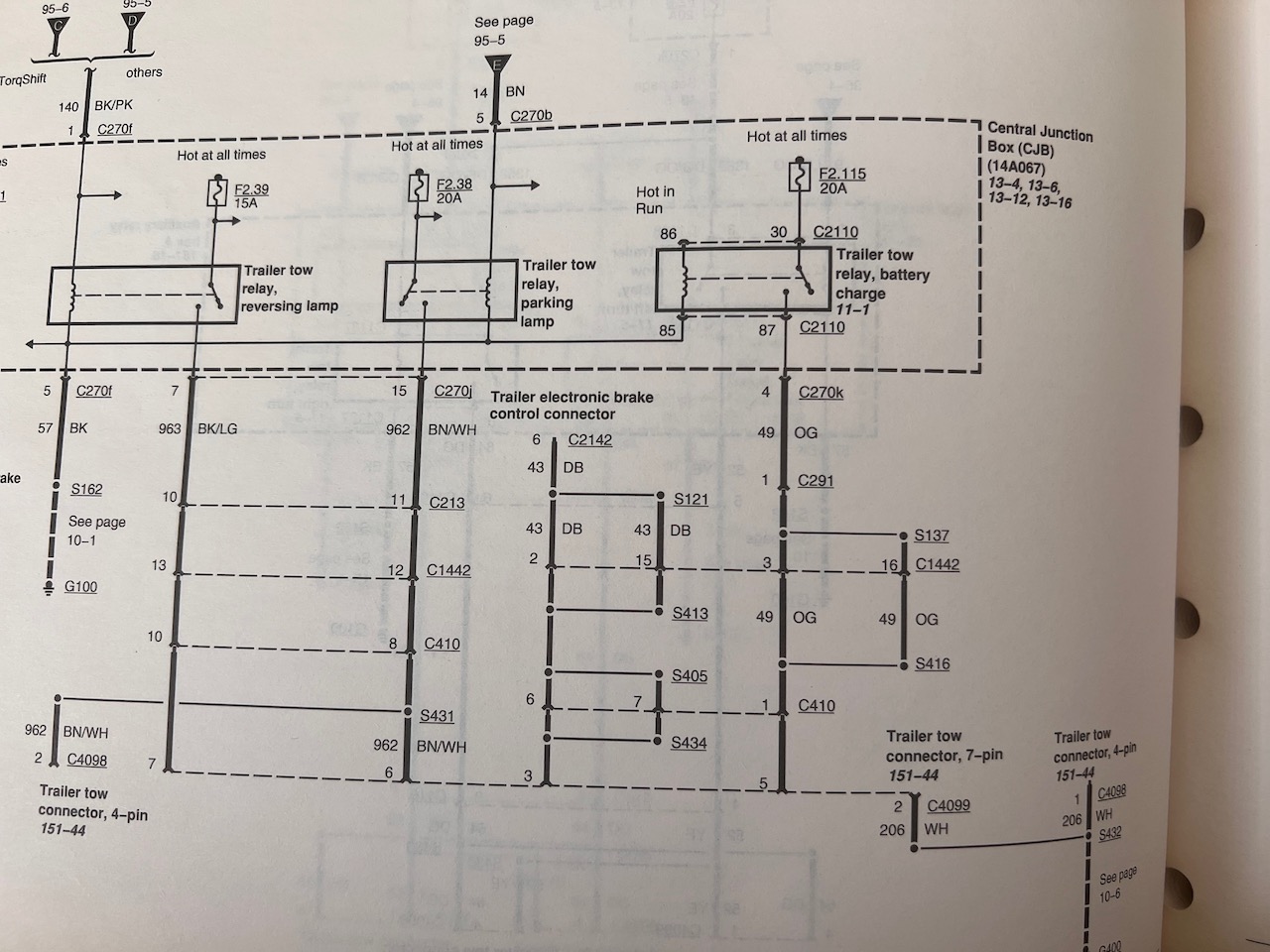
I pulled the schematics for my primary TV to be sure, and the good news is that there is a dedicated fuse for the tow connector and a relay that is energized only when the truck is in the run position. The bad news is that it is a 20A fuse, and not a 30A circuit, which may not work with the 20A DC-to-DC convertor I purchased.
 And thank you for mentioning the circuit protection; it has been part of my plan, I just hadn't gotten around to planning it yet. I do actually read the NEC from time to time  . Of course adding in a 12V distribution system, and putting the whole thing on wheels is uncharted territory for me... . Of course adding in a 12V distribution system, and putting the whole thing on wheels is uncharted territory for me...Here's my current thinking: AC Converter (60A): use short run (1-2ft) of 6ga with a 75A (?) circuit breaker DC-to-DC Converter (20A): use a short run (1-2ft) of 10ga with a 25A (?) circuit breaker. Not sure yet how I want to run the DC-to-DC output (directly to the battery behind a battery cutoff switch or infront of the switch to provide house power when the battery is disconnected). Also not sure of these CB values above - both values are well under-current for what the wire and battery can handle, but figuring the devices could push up to 20% past their rated output? I may be entirely wrong on this though. I'm also not sure if I should protect the +12V connection from the TV that comes through the 7-pin. In theory it is fused on the TV, and because it is connected to the DC input on the DC-to-DC converter I assume it won't be energized even when the battery connected to the DC output is. Assuming this is true, then I don't think I need any protection on this circuit. RE: coffee - the offer stands for the next time you visit the west coast! Thank you!!
|
|
|
2021 r-pod 193
|
|
|
|
|
StephenH
podders Helping podders - pHp

Joined: 29 Nov 2015 Location: Wake Forest, NC Online Status: Offline Posts: 6288 |
Post Options
Quote Reply
Posted: 31 May 2022 at 4:09pm |
|
I ran a dedicated 12V circuit when I installed my DC to DC charger. I installed a battery isolation solenoid in my Frontier to control it. The solenoid is triggered when the vehicle is started and de-energizes when the ignition is off. It goes to a 2-pole socket on the back of the Frontier and I ran a dedicated circuit for the DC to DC charger in the RPod that connects to that socket. Since it is only active when the vehicle is running, I could pull the trigger voltage for the DC to DC charger from that also without having to run another wire up to the vehicle. It was probably more complicated than it needed to be, but it works and works reliably.
|
|
|
StephenH
Happy is the man that findeth wisdom,... ouR escaPOD mods Former RPod 179 Current Cherokee Grey Wolf 24 JS |
|
|
|
|
offgrid
Senior Member
Joined: 23 Jul 2018 Online Status: Offline Posts: 5290 |
Post Options
Quote Reply
Posted: 31 May 2022 at 6:49pm |
|
I was one of the authors of the solar part of the NEC (article 690) back in the day. That was an interesting experience, you can imagine the process involved in getting Code written. Harder than hearding cats.
The first place to put a cb or fuse is the battery + terminal. That would be the source of the highest fault current. I recommend a bolt on fuse right at the terminal but if not as close as possible. So you don't need a fuse or cb on the DC/DC output since it is current limited but you do need one at the battery end of that circuit. You would however need one on the output if the installation instructions require it, because the instructions are part of the UL listing for the product, if not installed properly the product is not listed. So you need to follow both the NEC and the listings of the products when you install electrical systems. The thought process when designing overcurrent protection with multiple sources is to imagine a fault on each conductor and then tracing back in all directions to any sources of energy that could feed into that fault. Each and every conductor has to have properly sized overcurrent protection between it and the sources. The "25%" rule is to avoid nuisance cb trips or fuses blowing. So in general start with the max rated current of each device, multiply by 1.25, and pick the next highest available fuse or cb size. Then pick a conductor size with that ampacity or higher. For low voltage systems it's quite common to go higher in order to keep the voltage drops down. That's especially true for the long cable to a portable solar setup. In general you don't want the voltage drop on a circuit to be more than about 5%,or 0.6V on a 12V circuit for example. Yes I think the 20A DC/DC might be a bit much for a 20A supply circuit. You might want to see if you can either set it's max current a little lower if it's adjustable or return it and get one with a slightly lower current rating. Or run a new 10 gauge line via a 30A cb from the TV battery to the 12V 7 way pin. Then from the trailer side of the pin to the DC/DC input. You could still use the unused 7 way reverse pin to turn the DC/DC on and off. |
|
|
1994 Chinook Concourse
1995 RV6A Experimental Aircraft 2015 Rpod 179 - sold |
|
|
|
|
Post Reply
|
Page <12 |
| Forum Jump | Forum Permissions You cannot post new topics in this forum You cannot reply to topics in this forum You cannot delete your posts in this forum You cannot edit your posts in this forum You cannot create polls in this forum You cannot vote in polls in this forum |


