120-Watt Solar System for Rpod
Printed From: R-pod Owners Forum
Category: R-pod Discussion Forums
Forum Name: Podmods, Maintenance, Tips and Tricks
Forum Discription: Ask maintenance questions, share your podmods (modifications) and helpful tips
URL: http://www.rpod-owners.com/forum_posts.asp?TID=8970
Printed Date: 22 May 2025 at 2:18am
Software Version: Web Wiz Forums 9.64 - http://www.webwizforums.com
Topic: 120-Watt Solar System for Rpod
Posted By: Rustler
Subject: 120-Watt Solar System for Rpod
Date Posted: 31 Oct 2016 at 2:29am
|
I have been wanting to report on my implementation of a solar charging system on our 2016 Rpod 171. I had previously reported on progress made in an http://www.rpod-owners.com/forum_posts.asp?TID=8692&KW=Solar&PID=81473&title=new-solar-power-system-for-rpod#81473 - earlier forum posting . Due to a glitch in the website many of my earlier photos had been deleted. So here is an updated post of my completed solar system. I was guided by a couple of personal preferences in deciding how to proceed:
While our Rpod 171 has the “Solar Ready” SAE connector, I opted not to use it for the following reasons:
That SAE solar-ready connector can be used for an external (unfused) DC outlet.
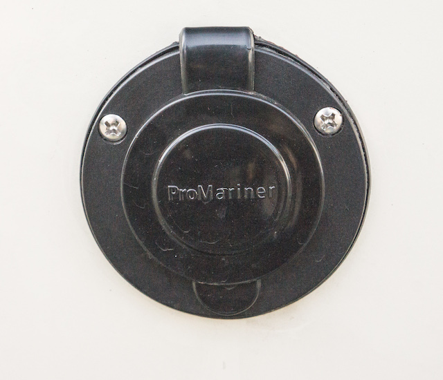
So I decided to locate a powerpole entry flange closer to the battery, that is on the left side near the front. Since I could not locate a suitable pre-made, water-resistant powerpole entrance connector, I fashioned one from a http://www.walmart.com/ip/Pro-Mariner-51201-Ac-Plug-Holder-Black/32930628 - ProMariner AC Plug Holder .
This is designed to hold the male end of a 3-prong AC extension cord, allowing a shore power cord to be plugged in. But I adapted this to hold a pair of powerpole connectors instead.
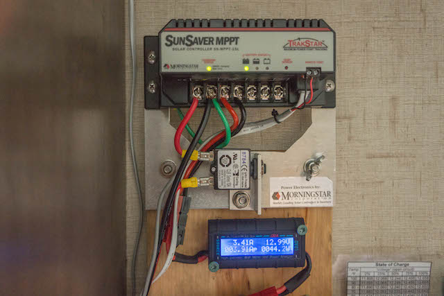
Part of my rationale for using a high voltage solar panel is that not only is the voltage higher, the current is correspondingly lower for the same power level. This lower current means any voltage drop due to wiring and connectors is less. Also that voltage drop is a smaller percentage of the higher voltage. So going from a 12 volt to a 24 volt panel lowers the percent voltage drop by a factor of 4 - half the current induced voltage drop and twice the comparison voltage. The up side of all this is you can go 4 times further with a given gauge wire having the same http://www.wholesalesolar.com/solar-information/voltage-drop - percent voltage drop . Thus when the trailer is parked in the shade, the solar panel can be located at some distance in full sun. I’ve been able to use 75 feet of http://www.solar-electric.com/10-2-tc.html - 10 gauge tray cable in this way to good advantage. By the way a 24-volt solar panel is no more dangerous that a 12-volt panel. Despite the higher voltage, current is limited to the short circuit output of the panel. This short circuit current is not much higher than the current at maximum power point, easily handled by properly sized wiring. In the case of my 120-watt solar panel maximum power is at 34.4 volts with 3.49 amps, while short circuit current is just 3.86 amps Using a 24-volt panel to charge a 12 volt battery is facilitated by a maximum power point tracking (MPPT) charge controller. This controller operates the solar panel at a voltage giving the greatest power. The voltage is then converted (at over 95% efficiency) to that necessary for charging the 12 volt battery. I installed my http://www.wholesalesolar.com/3615155/morningstar-corporation/charge-controllers/morningstar-corporation-sunsaver-mppt-ss-mppt-15l-charge-controller?gclid=CLzd3tKp5c0CFZA8gQod3ucPgg - Morningstar Sunsaver MPPT-15L above the left side window above the dinette seating, close to the powerpole inlet receptacle. For all interior wiring I used http://powerwerx.com/red-black-bonded-zip-cord - 10 gauge red/black zip cord .
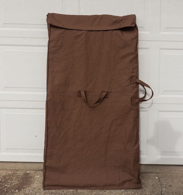
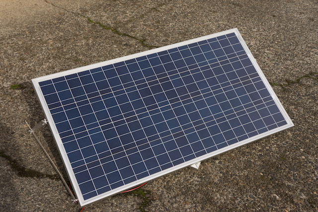
The solar panel I chose is the http://sunshineworks.com/downloads/24-volt-solar-panels/SLP120-24U.pdf - Solarland SLP120-24U from http://sunshineworks.com - Sunshineworks.com . My wife made a nice canvas cover to protect the panel while in storage or transport.
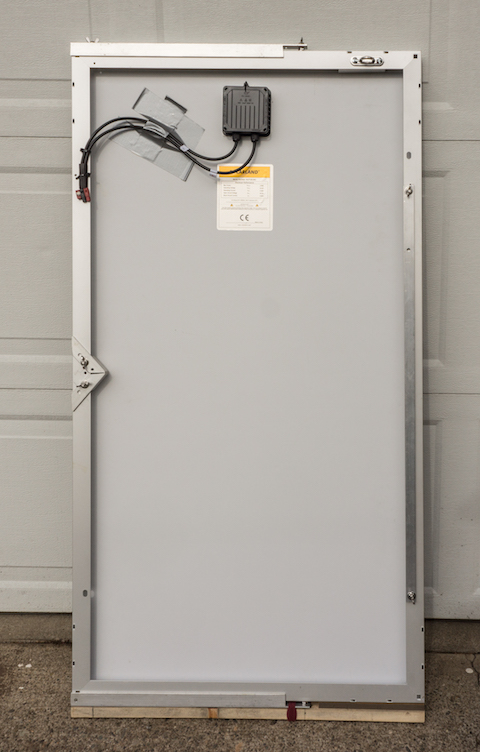
The next photo shows the back of the panel after removal from its canvas cover.
On top and bottom are aluminum support braces that swing out to tilt the panel up to receive sunlight. Stored along the right edge is a stack of the two bottom braces. On the left is the front center support in its stowed position. On the top right is a security loop attached to the panel with security screws, which cannot be unscrewed. This provides a point to attach a security cable to discourage theft. I have a 25-foot stainless steel cable for security if needed. This can be locked to the panel at the security loop. Finally on the bottom is a wooden piece that protects the bottom of the canvas cover from being damaged by the wing nuts holding the brace. All braces are aluminum, and all attachment bolts, nuts & washers are stainless steel.
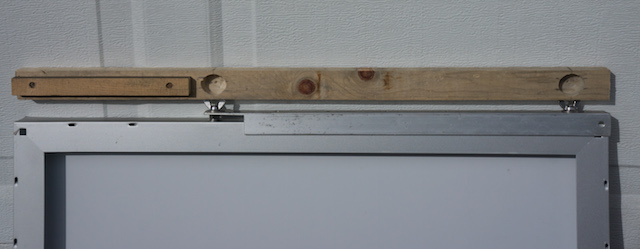
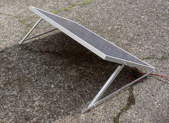
Above you can see one of the assembled braces. The front center support can be seen on the right flipped around to its extended position. This allows for three point ground contact for optimum stability. On top is the wooden protective piece covering the wing nuts. The next photo shows this wood piece removed.
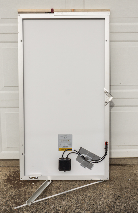
Above we see both brace assemblies and front center supporter deployed. Next photo shows the panel from the sunward side.
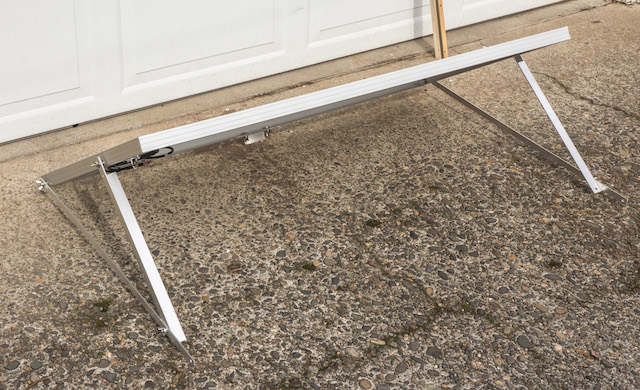
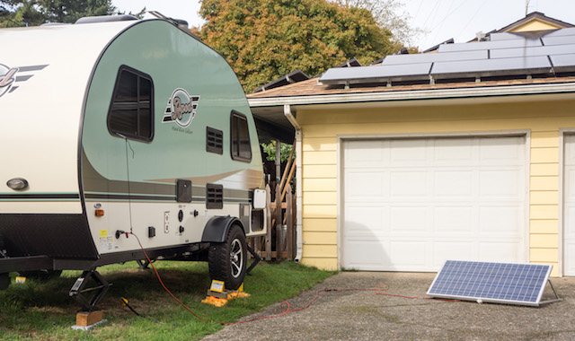
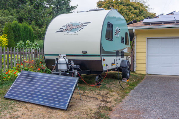
Next we see the panel deployed in the sun near the Rpod 171.
The horizontal bottom braces have holes drilled in different locations for changing their effective length to vary the tilt with the seasons.
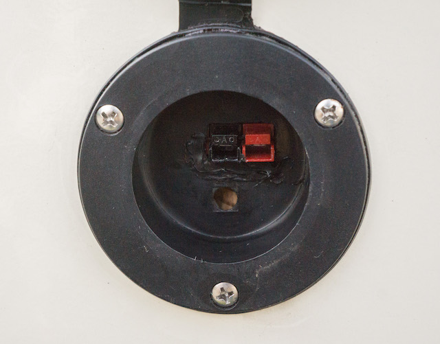
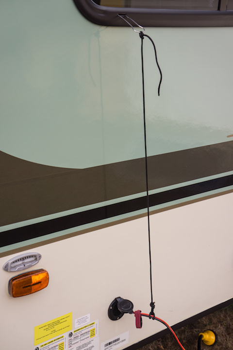
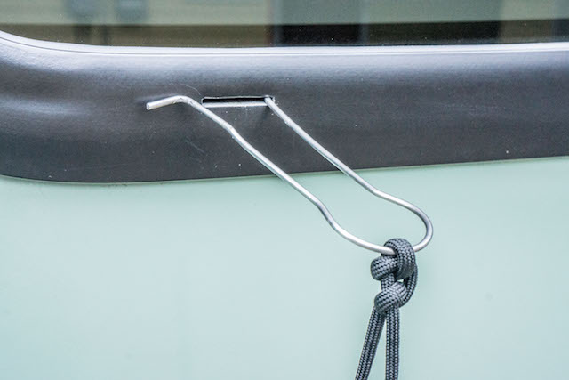
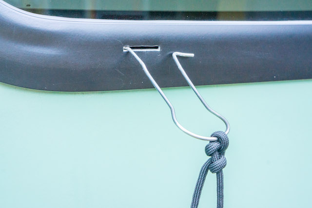
Above we can see the powerpole inlet jack with the 10 gauge zip line being supported by a length of black nylon parachute cord. This was necessary since the powerpole connectors are not designed to withstand a sideways or twisting force that could be exerted by the zip line. I needed an attachment point above to anchor the parachute cord. To provide this without drilling a hole in the Rpod wall I utilized the drain slot below the window as shown below.
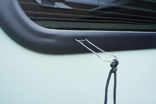
The wire used in the loop is a very stiff steel, which is difficult to bend. But it flexes enough to allow inserting the two ends into the drain slot, as shown in the photos below.
Below is the 120-watt solar panel deployed in the sun near our Rpod 171.
This panel is capable of around 8-1/2 amps at 13+ volts in full sun. This will allow for running a couple of refrigerator fans, lights and an Endless Breeze fan for personal cooling with enough spare current to provide for battery charging. It is hoped that this will be enough for boondocking with our Rpod 171. If necessary I can use a 185-watt 24-volt panel that I also have at my disposal.
I would rather not have to use that one since its larger size makes for difficult storage in the Rpod when traveling. But it does provide 13-1/2 amps charge current at 13 volts. My home-made solar panel setup is not as convenient as the Zamp or Renegy models. But it's a bit heaper and allows for a high voltage panel to be employed at some distance from a shaded travel trailer. I'll let you know how it all works out. ------------- Russ 2009 Toyota RAV4 V6 w/ tow package 2016 Rpod 171 HRE |
Replies:
Posted By: jato
Date Posted: 31 Oct 2016 at 4:56pm
|
Really interesting Russ. How much of an investment has this set you back thus far? Will be interesting to know how it works out in the real world. Please keep us posted!
------------- God's pod '11 model 177 '17 Ford F-150 4WD 3.5 Ecoboost Jim and Diane by beautiful Torch Lake "...and you will know the Truth and the Truth will set you free." |
Posted By: Rustler
Date Posted: 01 Nov 2016 at 12:13am
I hadn't really totaled it up before. But here's an estimate:
For comparison a 120-watt, 12-volt http://www.amazon.com/Zamp-Solar-120P-Charge-Kit/dp/B00K1LBROG/ref=sr_1_4?ie=UTF8&qid=1477978209&sr=8-4&keywords=120+watt+solar - Zamp solar panel with Pulse Width Modulation (PWM) controller goes for around $641. While it is a more polished and easier to use setup, it comes with the less expensive & inferior PWM controller. But the Zamp outfit is folding which makes for easier storage. http://www.amazon.com/ECO-WORTHY-Portable-Polycrystalline-Foldable-Suitcase/dp/B00MGLIIQO/ref=sr_1_2?ie=UTF8&qid=1477978034&sr=8-2&keywords=120+watt+solar - Ecoworthy and http://www.renogy.com/renogy-100-watt-12-volt-monocrystalline-foldable-solar-suitcase-w-o-controller/ - Renogy also make folding solar panels. The Solarland 24-volt solar panel is quite a bit more expensive than a similar 12-volt panel. The maximum power point tracking charge controller is more expensive than a similar pulse width modulating charge controller. But it will harvest a lot more energy from an expensive solar panel. And it allows using high voltage panels which will operate with less power and voltage loss. I can also use my 185 watt, 24 volt panel with the same controller. I will be using this solar charger at campgrounds without electric hookup and at each summer's Golden State Star Party. I might also make it to next year's Oregon Star Party. Both outings will be boondocking.
------------- Russ 2009 Toyota RAV4 V6 w/ tow package 2016 Rpod 171 HRE |
Posted By: mrharrybay
Date Posted: 09 Dec 2016 at 12:43pm
|
Well done! I've been thinking about adding solar for 2017 boondocking, do you feel the solar (any solar) will not run the air conditioning? That will be a deal-breaker for the Frau. ------------- 2015 RPOD 178, 2015 Chevy Colorado Z71 CC SB, Tekonsha Primus IQ, Lippert hitch, Cequent sway bar, countless nameless hitch pins who will give their lives while I learn how to back this thing up |
Posted By: Leo B
Date Posted: 10 Dec 2016 at 10:05am
|
Impressive!
------------- Leo & Melissa Bachand 2017 Ford F150 2021 Vista Cruiser 19 csk Previously owned 2015 Rpod 179 2010 Rpod 171 |
Posted By: furpod
Date Posted: 10 Dec 2016 at 10:59am
Boondocking and a/c are incompatible. The only way to run the a/c (reasonably) off grid is with a generator. Producing mains power from a battery bank for a sustained load isn't something easily, compactly, or cheaply done. Solar is used to recharge the batteries, nothing else. You don't "run" anything on solar. ------------- |
Posted By: mrharrybay
Date Posted: 10 Dec 2016 at 11:43am
|
Thanks, the dual battery set-up is also something that looks worth adopting for general efficiency, too. ------------- 2015 RPOD 178, 2015 Chevy Colorado Z71 CC SB, Tekonsha Primus IQ, Lippert hitch, Cequent sway bar, countless nameless hitch pins who will give their lives while I learn how to back this thing up |
Posted By: Tars Tarkas
Date Posted: 10 Dec 2016 at 9:39pm
Just to be clear, two batteries won't come close to running the air conditioning either. Not sure that's what you're thinking, but as Furpod said, there is no practical way to run the air con using battery power. Maybe with the back of a pickup truck full of batteries, but that would weigh at least half ton and I don't know how long that might work or what it would take to recharge the batteries. That would be quieter, but way more expensive than a good 2400+ watt generator. TT ------------- 2010 176 FJ Cruiser |
Posted By: mrharrybay
Date Posted: 11 Dec 2016 at 8:03am
|
No, not thinking that at all, dual batteries just seems like a good overall rPod practice which I should adopt. It's clear to me that a/c off the grid is only going to come from a generator. Thanks. ------------- 2015 RPOD 178, 2015 Chevy Colorado Z71 CC SB, Tekonsha Primus IQ, Lippert hitch, Cequent sway bar, countless nameless hitch pins who will give their lives while I learn how to back this thing up |
Posted By: Rustler
Date Posted: 12 Dec 2016 at 4:48am
Thanks for your kind comment. Best abandon any use of air conditioner except on shore power or mobile generator. It is just way too big of a power draw to run off solar/battery power. You would need a huge battery and inverter to supply the necessary AC power for the air conditioner. With boon docking one must of necessity do without some of the amenities available with commercial electric power. But I have camped out 4 nights (at the Golden StateStar Party) using just solar power and propane. It did allow using lights, and an Endless Breeze fan to move some air for personal comfort. The temperatures reached the mid-nineties each day. But that 185-watt panel had way more capacity than was needed. Even after my telescope running off battery power all night, the solar panel recharged the battery quickly each morning and kept up with daytime loads. ------------- Russ 2009 Toyota RAV4 V6 w/ tow package 2016 Rpod 171 HRE |
Posted By: jato
Date Posted: 12 Dec 2016 at 5:56am
|
Good to know, thanks for the update Russ.
------------- God's pod '11 model 177 '17 Ford F-150 4WD 3.5 Ecoboost Jim and Diane by beautiful Torch Lake "...and you will know the Truth and the Truth will set you free." |
Posted By: RickyTerzis
Date Posted: 19 Jul 2017 at 11:56am
|
Hi...i am a new user here. As per my knowledge there is no practical way to run the air con using battery power.
Maybe with the back of a pickup truck full of batteries, but that would
weigh at least half ton and I don't know how long that might work or
what it would take to recharge the batteries.
https://www.7pcb.com/contact.php - pcb assembly usa
|