Installing a Renogy 100 watt Suitcase solar Panel
Printed From: R-pod Owners Forum
Category: R-pod Discussion Forums
Forum Name: Podmods, Maintenance, Tips and Tricks
Forum Discription: Ask maintenance questions, share your podmods (modifications) and helpful tips
URL: http://www.rpod-owners.com/forum_posts.asp?TID=8194
Printed Date: 27 Jun 2025 at 8:30pm
Software Version: Web Wiz Forums 9.64 - http://www.webwizforums.com
Topic: Installing a Renogy 100 watt Suitcase solar Panel
Posted By: Pod People
Subject: Installing a Renogy 100 watt Suitcase solar Panel
Date Posted: 16 Jun 2016 at 9:31am
|
Adding a 100 watt Renogy Suitcase Solar System
Laura and I love to use our pod on long distance, multi-week travels. We like to stay for 3-5 days where we can. A lot of the National and state parks, wildlife refuges and BLM lands do not have power in their campgrounds. We want to stay in beautiful areas and still have the service of our refrigerator, heat, fans and minimal lights at least.
We have learned to conserve power. We use solar powered indoor lights, we have replaced all of the interior bulbs with LED’s, we don’t use the water heater and have purchased very good batteries for our RPod. We need the maximum power (amp hours) from our batteries. We purchased 2 Duracell EGC2 batteries from Sam’s Club. These are 6 volt golf cart batteries that when wired in series combine for 12 volts and 230AH. These batteries without recharging will last us about 2 -3 days with average power usage and minimal furnace usage. We should never let the batteries go below a 50% state of charge to avoid permanent damage. We still needed more power over a longer duration. The obvious answer was that we need a way to recharge our batteries.
I wanted to add a method to recharge the batteries without having to use a generator. So the obvious answer was to use solar power. I wanted to make it as compact as possible, yet also as versatile as possible. I did a lot of research and came across the Renogy 100 watt Suitcase solar system. This system is essentially a “plug and play” self contained solar system. It comes as a folding solar panel that is 20”x27”x3” when folded and weighs 27 pounds. It comes packed in a hard sided nylon padded case. It has a built-in charge controller and a set of lead wires connected to a set of battery clamps. Simply hook the cables to the battery and open the panels and you are charging your battery. Here is the website for the system:
http://www.renogy.com/renogy-100-watt-12-volt-monocrystalline-foldable-solar-suitcase-w-o-controller/ - http://www.renogy.com/renogy-100-watt-12-volt-monocrystalline-foldable-solar-suitcase-w-o-controller/
As I researched and thought through this process, I learned about RPod’s new Zamp solar system. I decided that a system that offered a remote panel rather than a permanently mounted panel made more sense. I wanted to be able to park the R Pod in the shade and still have sun available for the solar panel. I decided to use the Suitcase Panel, but use it remotely. This panel setup will allow me to locate the panel some distance from the Pod and allow sun on the panel and shade for the pod. Using a voltage drop calculator, I determined that we could locate the panel up to about 25 feet from the Pod with a 10 gauge wire and have minimal voltage drop (1.74 % or .25volts).
After thinking about the cost and weight of the necessary 25’ of 10 gauge wire, we realized that we already have 25 feet of 10 gauge wire that we carry with us all the time---the 30 amp power cord extension. We seldom need 50’ of power cord, plus if we are off grid we have no need for a power cord at all. So, I have designed a system to work using our extra power cord as the line cord between the suitcase solar panels and the Charge Controller. I called Renogy several times and spoke with their technical advisors. None of them had ever heard of their system being used this way. However, they all agreed that it should work fine.
I made up a parts list and ordered what we needed. Overall, this project cost less than $475-about ½ the cost of a Honda generator. Here is a list of the parts I bought from Renogy 100watt 12 volt Monocrystalline Foladable Solar Suitcase w/o Solar Charge Controller Renogy View Star 20 amp PWM Solar Charge Controller 20amp ANL fuse set w/ extra fuse MC4 assembly tools (2 specialized wrenches) MC4 set (of 5 waterproof connectors) 10amp inline fuse module Renogy does not charge taxes and shipping is free, plus they gave me 10% off for their Memorial Day Sale.
I bought these parts from an online RV parts supplier: 30amp female receptacle and cover 18” male 30amp pigtail
My total cost was under $475. I spent $396.93 with Renogy, $43.56 with an online RV supplier, $21.67 at Lowe’s for 10 gauge wire and assorted electrical parts and $5.85 at a local automotive store for 12 volt electrical connectors and battery cable. I had miscellaneous screws and hardware on hand. I spent a total of about 6 hours wiring and installing all of the parts and pieces. I am happy to report that everything worked the first time. I expect to get 3-5amps at 13-14.2 volts in full sun. That should replenish our batteries daily if we have good weather and be conservative in using electricity.
It was a fun project from start to finish. I learned a lot about solar power and am excited to see it work. The people at Renogy were very helpful in several discussions and technical calls. Their products appear to be well-made, get good reviews and have been available long enough to have a serviceable history. There are lots of You Tube videos concerning this product. This is the Renogy website http://www.renogy.com/ - http://www.renogy.com/
I am happy to report that everything worked the first time. I expect to get 3-5amps at 13-14.2 volts in full sun. That should replenish our batteries daily if we have good weather and be mindful of electricity consumption.
I hope you find this post informative and helpful. Laura gets much credit for editing, re-writing and great photos.
Travel safe
Vann
The rest of this post is a step by step description of how I did this project. Note that there are pictures at the end of the article.
The PROJECT The project was to connect the Solar Suitcase Portable Solar Panels using a standard 25-foot, 30 amp, 10 gauge RV extension cord (that we already owned) to the Pod batteries via a Charge Controller mounted inside the pod.
The Solar Panels and Power Cord: The Renogy 100 watt Suitcase Solar Panels are waterproof, but the Charge Controller that comes mounted on those panels is NOT waterproof. I wanted to mount the Charge Controller inside the pod to keep it out of the weather and be able to monitor the solar panel performance. So, I ordered the solar panels with the same Charge Controller but specified it NOT be attached to the solar panels.
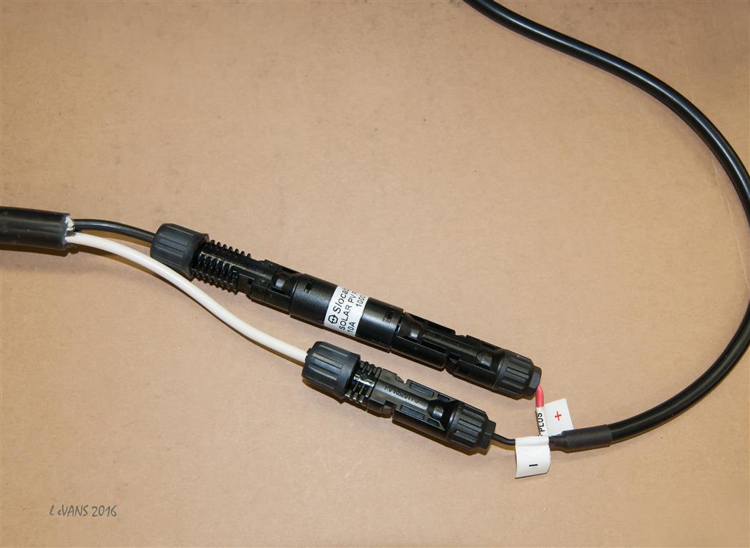
Wiring the solar panels to the Charge Controller requires waterproof electrical connectors. The solar panels come with 18” lead wires permanently connected to the solar panels and outfitted with built-in snap-connectors (MC4) at the other end. MC 4 connectors are a 2-part (male/female) snap system for waterproof electrical connections.
I purchased a kit of 5 MC4 connectors and the 2 proprietary wrenches required for assembly/disassembly. There are several videos on the Renogy site and You Tube that show you that assembling and connecting the MC4 parts is simple, reversible and effective using the proprietary wrenches.
The next step is to attach the male plug to the solar panels. I assembled the MC4 connectors on the end of the male pigtail leads. An in-line, 10-amp PV solar fuse module is required (on the positive wire) between the solar panel and the Charge Controller. I attached this fuse between the solar panel and male pigtail plug end. Note: This system does not need a ground of any type. Thus, we use only the hot and neutral wires and not the ground wire in the pigtail.
So finally, I was able to plug the solar panel’s male plug into the female end of my 25-foot RV extension cord.
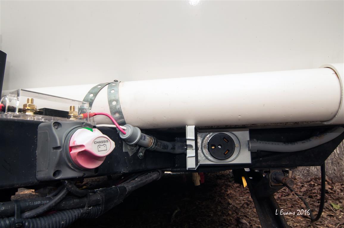
The next step was to mount the female 30 amp receptacle in a waterproof exterior box on the main frame under the front of the R Pod. Once the receptacle is installed, the male end of the extension cord will plug into it.
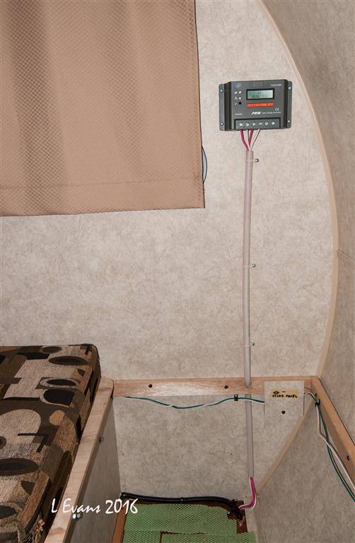
Now, I have to get the wires from the receptacle to the Charge Controller. The Charge Controller is located inside the pod as close to the batteries as possible. The 10 gauge wires from the female receptacle run in ½” PVC conduit to a hole drilled in the floor. I used a heat gun to customize the shape of the conduit. The wires come into the pod inside the front storage area under the dinette seat. I used PEX plumbing pipe as a conduit from the floor up to the Charge Controller. I connected the wires from the 30 amp receptacle to the solar panel input slots (positive and negative) on the Charge Controller. That completes the power input side of the project. Thus the entire sequence of power input consists of the solar panel with an inline 10 amp fuse plugged to the 25’ power cord which is plugged to the 30 amp receptacle which is hard-wired to the Charge Controller.
Power Output from Charge Controller to Pod Batteries I chose the PWM Charge Controller over an MPPT Charge Controller for our solar system. We have only one portable solar panel and it is under 200 Watts. So, we don’t need the considerably more expensive, higher capacity, higher efficiency MPPT Charge Controller.
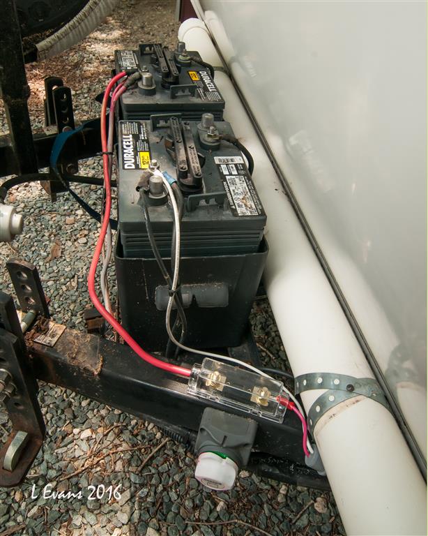
I connected the Charge Controller with 10 gauge output wires to the positive and negative terminals of the battery. I routed the wires from the Charge Controller down the PEX conduit, through the hole in the floor, through a short piece of PVC conduit, through the waterproof receptacle box, through another piece of PVC conduit and out the conduit end cap. The positive wire goes to a 20 amp ANL fuse block that I mounted on top of the Pod’s A Frame. I used a standard automotive battery cable to connect the fuse directly to the positive battery terminal. I used 10 gauge wire to connect the negative line directly from the Charge Controller to the negative battery terminal.
Charge Controller The Charge Controller has a small LCD screen with a number of menus, information and read-outs. It does not require any special programming; it is fully functional out of the box. However, the Charge Controller can be highly customized. The owners’ manual covers what you need to know.
For example, the Charge Controller has these standard screens: How much power is coming from the solar panels to the Charge Controller. How much power goes from the Charge Controller to the Batteries Batteries’ state of charge How much battery power is being consumed
This completes the project.
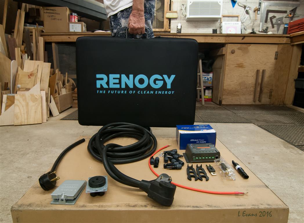
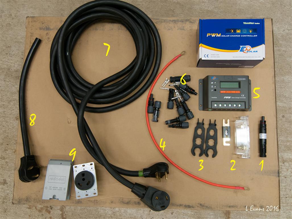
These are the basic materials needed for our installation
1. 10 amp PV solar inline fuse module 2. 20 amp ANL fuse unit 3. MC4 wrenches 4. 24” battery cable 5. Viewstar 20 amp Charge Controller 6. MC4 connectors 7. 25’ 30amp RV power cord 8. 18” male 30amp pigtail 9. 30amp female receptacle and waterproof cover
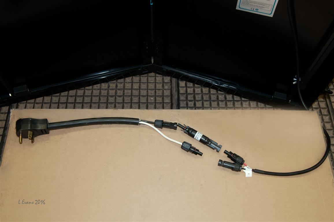
Male pigtail: The positive wire has a female MC4 end connected to the male MC4 of the 10 amp fuse. The female end of the 10 amp fuse is connected to the male MC4 end of the solar panel positive lead wire. The neutral (white) pigtail wire has a male MC4 which plugs into the female MC4 of the solar panel negative lead wire.
Note: This system does not need a ground of any type. Thus, we use only the hot and neutral wires and not the ground wire in the pigtail. Cut the green wire off of the pigtail.
The completed connection between the Solar panel and the male plug
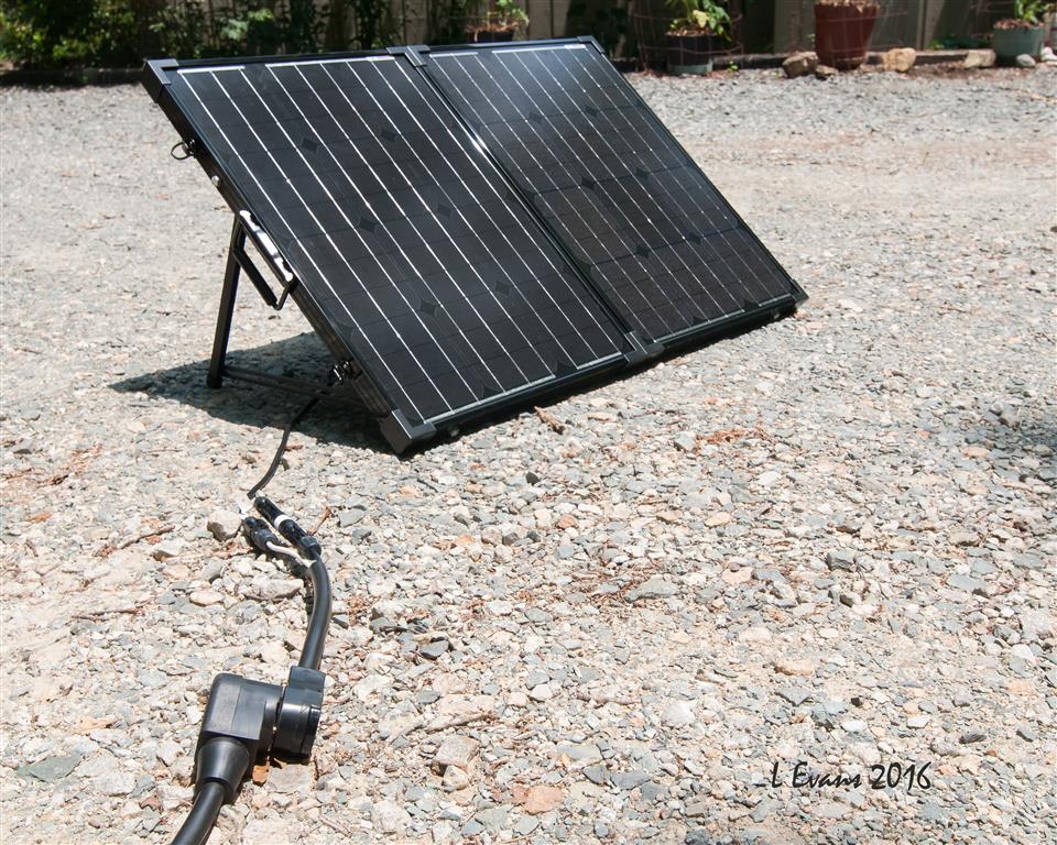
The input system - solar panel, inline fuse, 30amp plug connections between the solar panel and our 30 amp RV extension cord
30 amp receptacle mounted on front frame. ½” PVC conduit with positive/negative output wires from Charge Controller
Charge Controller mounted on wall, PEX plumbing pipe used for conduit
Dual 6v Duracell batteries wired in series (230 amp hours combined) and the 20 amp ANL fuse module
Everything hooked up
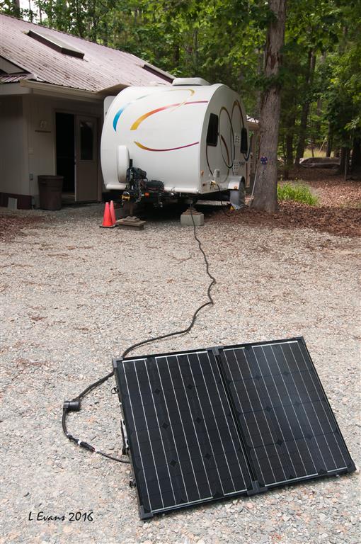
Panels are max distance from pod, Panels are in the sun Pod is in the shade We now have solar power to recharge the Pod's batteries!!
------------- Vann & Laura 2015 RPod 179 https://postimg.cc/0zwKrfB9"> 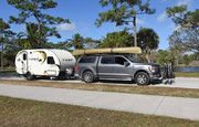
|

Replies:
Posted By: Don Halas
Date Posted: 16 Jun 2016 at 10:11am
|
The 30 cable adapter you made. Your 3rd photo looks like you have the male end coming off the solar panels. Is that correct? It is my understanding that the panels may produce voltage significantly higher than the 12 volts you'll get on the other side of the charge controller. If that's correct do you have any concern about the male end being live?
|
Posted By: Pod People
Date Posted: 16 Jun 2016 at 1:13pm
|
That's a good question. We did consider this. It was very hard to find a fixed waterproof male connection that could be mounted and wired, so the decision was essentially made for us-we had to use the female end on the trailer. I discussed this with the Renogy technical advisors and they said to make sure the 25' cord was attached to the male plug and also attached at the trailer before opening the solar panels and making the plug ends hot. They also added that in the unlikely event that it did short, the 10 amp inline fuse would blow. It is a simple twist -to-open fuse holder with a standard 10 amp glass fuse that is easily replaceable. The male end will have the 2 prongs exposed and could be shorted if the panels are open and both of the plug end touches something . I will wait and see if it becomes a problem. I could get a unwired female receptacle to cover the male end if it becomes an issue. Thanks for the question. I see you are also hooking up a solar system. I hope some of my post was helpful in your application. Vann. ------------- Vann & Laura 2015 RPod 179 https://postimg.cc/0zwKrfB9">
|
Posted By: Don Halas
Date Posted: 16 Jun 2016 at 1:52pm
|
For whatever it's worth my installation which I am going to complete this weekend will have connectors just before the charge controller so I can disconnect them and not worry about having hot leads coming from the solar panel.
I know it's low voltage, but never a good idea to have it exposed. |
Posted By: bluecatjudy
Date Posted: 16 Jun 2016 at 5:08pm
|
Great Mod and information. I also installed a 100watt Renogy solar panel on my Rpod this week. I have a 2016 179 with the solar plug already installed. I crawled under the stove and rerouted the wires going to the plug. I mounted a 30A Renogy Adventurer controller in the cabinet as you walk in the door. I know it was over kill for a 100 watt solar panel but it mounted flush with the cabinet and no wires exposed. I used an inline fuse at the controller and another in the battery box. I bought 20 feet of wire from the panel to the solar plug. i was getting 5.5 amps after plugging it in. I like the led display and convenience of plug and charge. My wife made a sunbrella cover for it when we are traveling and we store it in the bathroom. We should have a contest who gets the best charge. Of course there is other variables not just your cord. I get more sun in Florida but I have noticed on my boat's solar panel it charges better in colder weather. I would post a picture but for the life of me I can not figures it out. Can anyone help me? I am on a Mac book pro.
------------- sailorman |
Posted By: Westgl
Date Posted: 19 Jun 2016 at 5:23pm
|
I have a 2017 179 and also have the renogy 100w solar suit case panel. I would love to see a picture of were you mounted the controller at. did you remove the controller that comes mounted on the renogy panels and relocate it inside the pod? If so I like that idea. keeps the controller out of the wet weather as it is not weather proof, but solar panels are weather proof, just incase a storm sneaks up on you, the controller would be safe, I like it!!! I would love some pictures.
------------- 2010 RAV4 V6 2017 RPOD 179 Hood River Edition Dual 6 volt Batts Dual propane Tanks Batt Disconnect Bed leg extension Dinette modification Renogy 100w solar Motorcycles several currently |
Posted By: bluecatjudy
Date Posted: 19 Jun 2016 at 11:25pm
|
I have been trying to upload pic but i am new to the forum and have not "got" it yet. I bought a 100 watt panel with no controller. It was about $120 on Amazon. I bought the controller separately for $75 on eBay. It is flush mounted so you see no wires and mounted it in the counter as you walk into the tt. It's a great controller as it tells me volts at the battery, volts at the panel and amps. It has option for temperature but the wires are only about 6 feet. If you crawl under the cabinet there is a panel easily removed from the back which will expose the wires from the solar port. Cut the wires at the splice and run those to the battery side of controller. Spice 4 feet 10 gauge wire from Home Depot to the port and run it to the solar panel side of controller. Add 2 fuses and wire from the solar panel to the port;and, your done. ------------- sailorman |
Posted By: Pod People
Date Posted: 09 Jul 2016 at 9:39am
|
I have added a female end for the male plug that is connected to the solar panels. This will prevent any accidental exposure to a shock if someone touches both contacts of the male plug. It essentially a yellow "hockey puck" 15 amp to 30 amp adapter . Vann ------------- Vann & Laura 2015 RPod 179 https://postimg.cc/0zwKrfB9">
|
Posted By: JandL
Date Posted: 09 Jul 2016 at 8:29pm
|
The solar panel outputs a DC voltage and the MC4 connector coming off the panel are very good sealed connectors for DC voltage. Adding the extra AC connector is not how I would have done it. It’s not a good idea to mix AC and DC connectors. Someday someone might not be paying attention and plug the wrong power source into the wrong connector. If you need to add a DC panel mount connector[ https://powerwerx.com ] carry’s Anderson Powerpole connectors. Also Marinco makes a panel mount ConnectPro Plug & Receptacle for Trolling Motor, 3 wire which will take up to a 8 gauge wire and a 2 Wire ConnectPro Receptacle and Plug Combo, 2 wire that take up to a 10 gauge wire. The ANL fuse is going to give you problems as it will start to corrode due to exposure to the weather. You could use a Bussmann HHR ATC Holder Waterproof fuse holder with locking cap, up to 30 amps, 12 gauge leads also White Products has the same thing in 10 gauge [ http://www.whiteproducts.com/sfh-ato.shtml ] this fuse holder would easily fit under your battery cover. Two other good sites for Automotive wiring are Del City [ http://www.delcity.net ] and Waytek [ https://www.waytekwire.com ] ------------- JandL 2013 Honda Ridgeline 2012 177 2 Paynes in a Pod |
Posted By: WillThrill
Date Posted: 09 Jul 2016 at 9:03pm
I'm no electrician, but why would it be bad to mix AC and DC connectors? Electrical current doesn't care what kind of wiring it's flowing through. I know that AC and DC breakers are different, along with electrical board components, but connectors for solar panels? I agree that the ANL fuse holder needs to be sealed somehow to prevent water intrusion.
------------- "Not all those who wander are lost." Tolkien 2014 Hood River 177 2005 GMC Envoy XL |
Posted By: JandL
Date Posted: 09 Jul 2016 at 11:00pm
|
"I'm no electrician, but why would it be bad to mix AC and DC connectors?"
Someday someone might not be paying attention and plug 120 volts AC into your panel. ------------- JandL 2013 Honda Ridgeline 2012 177 2 Paynes in a Pod |
Posted By: WillThrill
Date Posted: 09 Jul 2016 at 11:53pm
Well I can't imagine someone else using my solar panel on my Pod except me, but I see your point. I have never found a need to put a 120 volt AC plug on a solar panel anyway though. ------------- "Not all those who wander are lost." Tolkien 2014 Hood River 177 2005 GMC Envoy XL |
Posted By: Rustler
Date Posted: 10 Jul 2016 at 12:23am
That is an understandable concern, Don. In most cases this would be an issue. But with a solar panel the output can safely be shorted without dire results. On the back of many solar panels is sticker giving operating characteristics of that particular panel. For example my 185 watt Shuco panel has the following on its label:
The parameter of concern is that last one - short circuit current. In most cases if you short circuit a power source, the current will rise until something burns out and/or a fire happens. Not so in the case of a solar panel. If I were to short circuit the output of my solar panel, the 5-1/2 amp current can be safely handled by most any reasonably sized wire in the circuit. It's just the nature of how solar panels work. In contrast to other sources of power, the maximum current my panel can deliver is 5-1/2 amps. Even a continuous short circuit is passing only slightly more current than at the maximum power point (5.481 vs. 5.112 amps). So it does no harm to short circuit the output of a solar panel. You are correct that a solar panel can operate at significantly higher voltage than its rated voltage. Its operating voltage is determined by the load connected to it, that is the external circuitry attached. This is how a maximum power point tracking controller works. It varies the load until the product of volts and amps is maximum (maximum power output). In the example of my solar panel with output short-circuited, the external circuitry (the short circuit) holds the voltage at zero volts, with the current being 5.481 amps. The power being dissipated is zero. 5-1/2 amps X 0 volts = 0 watts. No dire results. But I do agree with what others have stated in this thread that there are some valid issues with the method used to wire the panel to the Rpod. While I applaud the ingenuity shown in using the 30-amp AC shore cord to attach the panel, it is very likely in violation of the National Electrical Code (NEC). While I don't understand the reasons for certain code requirements, they have been shown by experience (i.e. fires) to be necessary to prevent damage to wiring, associated living spaces and occupants. Using a 30-amp AC receptacle on the Rpod might invite someone unfamiliar with how it is wired up to assume it is meant to carry a 120 volt AC current. Of course that would require the use of a cord with male connectors on each end - not a standard type of cord. But if the Rpod was sold to someone unfamiliar with how it was wired there could be problems. With a likely violation of the NEC there might be liability issues. On the solar panel end a live shore power cord could be connected to the male pigtail. Hopefully someone foolish enough to do that would be protected by the circuit breaker on the AC circuit. But the results to the panel might not be good. 'nuf said. ------------- Russ 2009 Toyota RAV4 V6 w/ tow package 2016 Rpod 171 HRE |
Posted By: WillThrill
Date Posted: 10 Jul 2016 at 12:09pm
Does the NEC apply to RVs? I was under the impression that it only applied to fixed structures and mobile homes. ------------- "Not all those who wander are lost." Tolkien 2014 Hood River 177 2005 GMC Envoy XL |
Posted By: Pod People
Date Posted: 10 Jul 2016 at 1:24pm
|
Thanks to every one for their comments about our installation. Laura and I are both very aware of the potential problems while using the 30amp shore power cord and associated male plugs and female receptacles, we have practiced connecting everything in the correct order and fully understand so as to be safe and not be exposed to potential shocks or damage to our systems. Some of those issues were known before we did the install and we consulted with the technical staff at Renogy . some issues have surfaced in the posts since we started. We have tried to address these if possible. Thanks for all of the suggestions and input. We feel like the results will be very positive for our situation. We also feel that the installation is safe even if not applicable under the NEC . IF we sell our RPod, we will certainly be very forthcoming and instructive about the installation and operation of the entire system. We have certainly learned a lot over the last few months thanks to all of the smart people on this forum. We look forward to learning more and using our new solar installation Vann ------------- Vann & Laura 2015 RPod 179 https://postimg.cc/0zwKrfB9">
|
Posted By: JandL
Date Posted: 10 Jul 2016 at 1:31pm
|
Will Thrill asked "Does the NEC apply to RVs? I was under the impression that it only applied to fixed structures and mobile homes."
There are many standards that apply to trailers, one set of standards is the from the Recreation Vehicle Industry Association (RVIA) RVIA ANSI-Accredited Standards http://www.rvia.org/?ESID=ANSI RVIA Adopted Standards 120-Volt Electrical Requirements as specified in Article 551 and other applicable sections of NFPA 70, of the National Electrical Code. http://www.rvia.org/?ESID=adopted The NFPA 70, 2014 Edition of the National Electrical Code (NEC) has the following covering trailers. (Among dwelling types, mobile homes have the highest rate of fire. Article 550 addresses some of the causes of those fires with the intent of reducing these statistics.) Article 550 Mobile Homes, Manufactured Homes, and Mobile Home Parks ............................... 70–510 I. General ......................................... 70–510 II. Mobile and Manufactured Homes .......... 70–511 III. Services and Feeders ......................... 70–518 551 Recreational Vehicles and Recreational Vehicle Parks ....................................... 70–519 I. General ......................................... 70–519 II. Combination Electrical Systems ............ 70–521 III. Other Power Sources ......................... 70–521 IV. Nominal 120-Volt or 120/240-Volt Systems .......................................... 70–522 V. Factory Tests ................................... 70–530 VI. Recreational Vehicle Parks .................. 70–530 552 Park Trailers ....................................... 70–532 I. General ......................................... 70–532 II. Low-Voltage Systems ........................ 70–532 III. Combination Electrical Systems ............ 70–534 IV. Nominal 120-Volt or 120/240-Volt Systems .......................................... 70–534 V. Factory Tests ................................... 70–541 ------------- JandL 2013 Honda Ridgeline 2012 177 2 Paynes in a Pod |
Posted By: Rustler
Date Posted: 10 Jul 2016 at 4:45pm
You are right about the NEC not being directly applicable to recreation vehicles. But it is certainly has many principles that are incorporated in applicable RV standards. A quick search on the web shows the industry is guided by http://www.rvia.org/?esid=standards - standards found in ANSI, NFPA, NEC and others. The recreation vehicle industry is bound by these rules in producing RVs that are safe. I guess a point to keep in mind is that without knowing these standards it would be easy to concoct a solution to some wiring problem that is in violation of these safety standards. ------------- Russ 2009 Toyota RAV4 V6 w/ tow package 2016 Rpod 171 HRE |
Posted By: WillThrill
Date Posted: 10 Jul 2016 at 5:04pm
I was thinking along the same lines. When it comes to RVs, it's probably not legally enforceable as it usually is with structures and is more like guidelines. For the most part, I think that following the NEC makes good sense, at least from a safety standpoint, but there are some potential RV situations where a little fudging isn't going to cause a real problem. ------------- "Not all those who wander are lost." Tolkien 2014 Hood River 177 2005 GMC Envoy XL |
Posted By: sailor323
Date Posted: 11 Jul 2016 at 8:43am
The panels do not present any danger of shock. |
Posted By: bigcat
Date Posted: 04 Jan 2017 at 11:33pm
|
Bluecatjudy, I love the idea of using the solar port already installed on newer pods. I've read that the Zamp port that's installed on my 2017 179 has a proprietary conector. Did you have any issues wiring the solar panel to the preinstalled port?
Thanks! ------------- Big Cat 2017 179 |
Posted By: Hayduke
Date Posted: 05 Jan 2017 at 2:46pm
Not proprietary. It is a simple SAE 2-pin connector. You can find them just about anywhere that sells auto/RV electrical supplies. 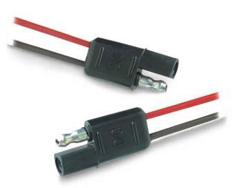 ------------- 2012 177 HRE 2017 Tacoma Double Cab |
Posted By: bigcat
Date Posted: 05 Jan 2017 at 3:37pm
Awesome! So all I would need to do is splice an SAE 2-pin conncetor on the end of a solar extension cord and it plug it into the solar port on the side of my pod, right? Thanks! Ty ------------- Big Cat 2017 179 |
Posted By: bob-Pod
Date Posted: 05 Jan 2017 at 9:25pm
|
Make sure you use a volt meter to verify which connector on the pod is positive and which is negative. I set up the output wire of my renogy suitcase so I could plug and play into the zamp port. Being aware of the extra wire length to the zamp connector to the battery, I also hooked up hooked up connectors at my batteries. If the sun is to the rear and I am in the shade, I will use the zamp port. If the sun is closer to the front I connect at the batteries. ------------- 2015 RPOD 178 HRE (2015- ) 2010 RPOD 171 (2009-2015) 2010 Toyota Tacoma Quad Cab |
Posted By: bob-Pod
Date Posted: 05 Jan 2017 at 9:29pm
|
You can get the SAE connector with 10 gauge wire at amazon. Don't get the 16 gauge. ------------- 2015 RPOD 178 HRE (2015- ) 2010 RPOD 171 (2009-2015) 2010 Toyota Tacoma Quad Cab |
Posted By: Rustler
Date Posted: 09 Jan 2017 at 10:21pm
The biggest problem with the Zamp solar port is that it is (unnecessarily) located very far from the battery. Unless the wiring is of very large gauge there will be a lot of voltage and power loss. I don't see why they didn't locate the port near to the battery. There's no reason they couldn't have done so. Also the SAE connector isn't the best for low voltage loss. Powerpole is much better. Of course this doesn't mean the Zamp port won't work. But I would be tempted to move the port nearer to the battery. ------------- Russ 2009 Toyota RAV4 V6 w/ tow package 2016 Rpod 171 HRE |
Posted By: Rustler
Date Posted: 09 Jan 2017 at 10:25pm
That's a good move. You get the best of both port locations. ------------- Russ 2009 Toyota RAV4 V6 w/ tow package 2016 Rpod 171 HRE |
Posted By: dropkick
Date Posted: 09 Mar 2017 at 3:14am
|
Nice! I did something very similar! Have a couple of Renogy 100W "suitcases" with and without controllers as well as a flexible panel. I replaced all the MC4's with 15-30A sized Anderson Powerpoles as they are easier for the family to figure out and disconnect... color coded and non-locking. Everyone understands red-to-red, black-to-black, and you can't mate them backwards anyways. Also allows for easy paralleling of a 2nd suitcase. I left the renogy controller on the one suitcase but never use it--good for charging external batteries via clips or other uses tho. We have a 177 and another small trailer each with their own Morningstar charge controller inside the electrical compartments (under the driver's side dining area seat box in the 177). I used Marinco's 2-wire trolling motor plug and receptacle on both trailers. (They also make 3 and 4 wire ones). Just mounted it thru the wall on the drivers side of the Pod so the wires go right into the dining seat box. The flap is waterproof when closed and actually so is the plug via an o-ring. Very small and clean installation. The plug end does leave the solar voltage exposed but it's not enough to worry about. We can always plug it in first, then connect the solar-end of the cable to the panel as powerpoles are insulated in both directions at all times. As for the cable, I found 10 or 12ga duplex brake cable worked well--cause I already had some. It looks like romex, is just as lightweight, is rugged, yet is stranded and rolls up cleanly. Easy to make custom lengths for various applications. SJOOW would work too of course. I didn't run the charger output straight to the battery, rather to the load side of the meter shunt in the power area so I can see the (negative) system current which is my solar output. 2 GC2's for batteries up front. As you've found, 100W should be enough with good sun and conservative usage. Can always add more! I would like to sometime put a small panel up top just for floating it in the driveway. https://powerwerx.com/anderson-power-powerpole-sb-connectors http://www.marinco.com/en/products/connect/trolling-systems/2-wire http://www.wiringproducts.com/duplex-brake-cable |
Posted By: Dromsie
Date Posted: 15 Mar 2017 at 5:42pm
|
I too have a Renogy panel, mine has the controller mounted to the panel. I called Renogy and they were pretty firm on not exceeding the 10 ft wire length between the controller and the battery. Given the Zamp connector is at the rear of the trailer, I'm assuming I will be far greater than the 10 ft length and thus may experience voltage drop that causes my batteries to charge at the wrong voltage. Here are my 3 questions: 1). Can I use a multimeter when the panel is hooked up to verify the actual voltage at the battery being sent by the panel? If so, what is this value? 2). Can the settings on the controller be changed to compensate for the longer wire between the controller and the batteries? Ideally I would like to keep the controller on the panel and have at least a 10 ft wire (so probably 20-25ft total with the wire run from the Zamp connector to the battery). If this is possible, does anyone know what the longest total run I can have is? 3). If #2 isn't possible, seems to me the best solution is to disconnect the controller from the panel and mount inside the Pod with the input coming from the Zamp and the output going to the battery and being roughly 10 ft. Do I have this correct? Thanks, Seth |
Posted By: Rustler
Date Posted: 15 Mar 2017 at 11:59pm
Seth, I would think the worse that would happen is that the voltage seen at the battery would be a bit less than the control would like. But as the charge current drops toward zero the voltage difference would become less and less. It might take a bit longer to get the battery to full charge. But it would eventually get to the same fully charged state. As for your questions:
Lets us know how it works for you. Russ
------------- Russ 2009 Toyota RAV4 V6 w/ tow package 2016 Rpod 171 HRE |
Posted By: john in idaho
Date Posted: 16 Mar 2017 at 9:51am
| I don't have a solar setup yet. One thing that concerns me is theft. Have you thought up any solutions? |
Posted By: Rustler
Date Posted: 17 Mar 2017 at 3:46am
While it would be hard to deter a determined thief, I have taken actions to discourage an easy theft of my solar panel. While I could have tied a vicious pit-bull to the solar panel, I'll try to describe what I did instead. On the frame of the solar panel I installed a stainless steel flanged loop held on by security screws. Such screws can only be tightened (clockwise) using a flat blade screwdriver. The security screw has no purchase for the screwdriver to turn it in the opposite direction. It is strictly clockwise tightening only. Threaded onto the screws on the inside side of the frame, there are nuts and lock washers. These are situated behind an L-shaped aluminum extrusion that blocks wrench access to the nuts. So while the security screws can easily be tightened up to secure the loop, they would be almost impossible to remove. The stainless steel loop is used as an attachment point for a stainless steel cable (of suitable length) that is attached to the trailer frame or other non moveable object. The cable is attached to the solar panel by a standard padlock. Each end of the cable has permanently formed loops. I had this cable made at a local marine supply hardware store. They were able swage the loops on each end without charge. I just paid for the hardware. They make up cables like this for such things as guy lines for sailboat masts. The solar panel is thus locked to a cable securely attached to the trailer. So someone just walking by couldn't easily grab the panel and run. Of course someone using a bolt cutter or hacksaw could, given enough time, defeat the whole scheme. But with everything out in public view that would be less likely. It took quite a bit of contortion to get the nuts and lock washers (located behind the extrusion) to thread onto the security screws. But it can be done with effort. Once threaded on, the whole assembly tightens up quickly and easily. This is particularly so once the lock washers begin to grip the nuts. I'll try to get some photos showing the security loop and how the cable is secured to the trailer frame and the solar panel. Such details are hard to describe in words. I hope this writeup will be of use to those wanting to provide a bit of anti-theft security for their solar panel. ------------- Russ 2009 Toyota RAV4 V6 w/ tow package 2016 Rpod 171 HRE |