
|
|
Post Reply 
|
Page <1 2122232425 33> |
| Author |
 Printable Version Printable Version Google Google Delicious Delicious Digg Digg StumbleUpon StumbleUpon Windows Live Windows Live Yahoo Bookmarks Yahoo Bookmarks reddit reddit Facebook Facebook MySpace MySpace Newsvine Newsvine Furl Furl Topic Search Topic Search  Topic Options Topic Options
|
texman 
Senior Member 
Joined: 24 Jul 2014 Location: TeXas Online Status: Offline Posts: 446 |
 Topic: Texman 182g Mods Topic: Texman 182g ModsPosted: 15 Feb 2019 at 9:11am |
|
Here is my take on the meter at this point: wiring: Red for meter power, yellow wire measures watts and mine is connected to + battery cable, white is ground. only problem is the lead to the donut (Hall sensor) is only about 12" long. It must be extended unless you are mounting in the battery box. Other reviewers had already done that and said no change in readings were noted. I added about 60" to the sensor with 20 ga solid copper. it has three wires that have to be matched. My sensor has the lead from the battery to the board passing through it behind the board. The meter itself does not come with a bezel for mounting, so plan accordingly. Getting the meter cleared to zero for current readings should be done prior to mounting i think. Since mine was mounted, i had to jump wires from the meter straight to the battery to get a zero measurement to start with. you have to have power to the meter to clear the current measurement, so if you are running on battery, the sensor must be not in place. and, the meter will not clear unless the sensor is present. The instructions are ok, but lack proper or even normal English so a bit had to follow on some items. THe meter readings for current are right on with my Klein at currents above 1 amp. The meter only measures current to 1/10th of an amp. So it may just be rounding when looking at milliamps. not sure yet. I really like that the meter keeps a cumulative amp in/amp out measurement and it is settable to the total amp hours of your particular battery setup. As long as accuracy is good, it should give me close to a fuel tank like setting for the batteries. Relying on voltage reading is good as well, but when batteries are under load the voltage does not read the same as a resting battery. The meter allows you to clear the cumulative amps in/out when needed to establish a baseline. For instance when you just started a boondock session and want to see if you are over or under what you are getting from solar. edit: and after doing some reading hall sensors are "notorious" for being inaccurate. quote :Since the Hall sensor is not directly connected to the current-carrying
wire, outside forces can cause significant error in the magnetic field
measurements [1]. The earth’s magnetic field alone can cause a 0.4 A
error, not to mention the fields generated by other coils, conductors,
and electric motors / generators internal to the vehicle [1]. Being
in-circuit means an IBS allows far fewer errors from outside
interference compared to a Hall Effect sensor. The maximum current
sensing error under any in-car condition for an IBS unit should be 0.5 %
plus offset (30 mA), which is the same error that can be observed due
to the earth’s magnetic field in the Hall Effect sensor just by changing
directions with 80 A of current flowing [1]. so i think at this point i will conclude with this: it is good enough for who it is for. At least for now anyway. A shunt system is more accurate but has some disadvantages as well.
|
|
 |
|
|
GlueGuy
Senior Member

Joined: 15 May 2017 Location: N. California Online Status: Offline Posts: 2627 |
Posted: 15 Feb 2019 at 10:32am |
|
Congratulations on getting it together and outlining for the rest of us some of the ins and outs. Hall effect sensors are great, in fact there's one in that Klein meter of yours (and mine). It's currently the only way I know to get a non-invasive measure of DC current. A couple of things you did not mention about them is that they require an accurate bias-voltage in order to operate, and that both the bias voltage mechanism as well as the hall-effect circuit need to be temperature compensated. That's something you may not find in less expensive iterations.
None-the-less, I think it will work very well for you. We have a few dozen neighbors who have off-grid solar systems, and I know of a few that have a similar power-in/power-out meters separate from their charge controllers and inverters.
|
|
|
bp
2017 R-Pod 179 Hood River 2015 Ford F150 SuperCrew 4WD 3.5L Ecoboost |
|
|
|
|
offgrid
Senior Member
Joined: 23 Jul 2018 Online Status: Offline Posts: 5290 |
Posted: 15 Feb 2019 at 11:04am |
|
The traditional way to measure dc current is using a current shunt. Those are rock solid and accurate, I'd recommend them over hall effect sensors for permanent installations. For temporary clamp ons, the hall effect sensors are great, just zero them immediately before each measurement and keep them away from magnetic fields.
I last got bit on this trying to use my hall effect clamp on to measure brake magnet current and wondered why it was different every time I took a reading. Duh.
 |
|
|
1994 Chinook Concourse
1995 RV6A Experimental Aircraft 2015 Rpod 179 - sold |
|
|
|
|
texman
Senior Member
Joined: 24 Jul 2014 Location: TeXas Online Status: Offline Posts: 446 |
Posted: 15 Feb 2019 at 11:06am |
|
off grid-that actually make sense to me now.
 i have been learning.... i have been learning.... |
|
|
|
|
offgrid
Senior Member
Joined: 23 Jul 2018 Online Status: Offline Posts: 5290 |
Posted: 15 Feb 2019 at 11:55am |
|
And I seem to be constantly relearning stuff I used to know. Comes with age I guess.

|
|
|
1994 Chinook Concourse
1995 RV6A Experimental Aircraft 2015 Rpod 179 - sold |
|
|
|
|
texman
Senior Member
Joined: 24 Jul 2014 Location: TeXas Online Status: Offline Posts: 446 |
Posted: 18 Feb 2019 at 6:03pm |
|
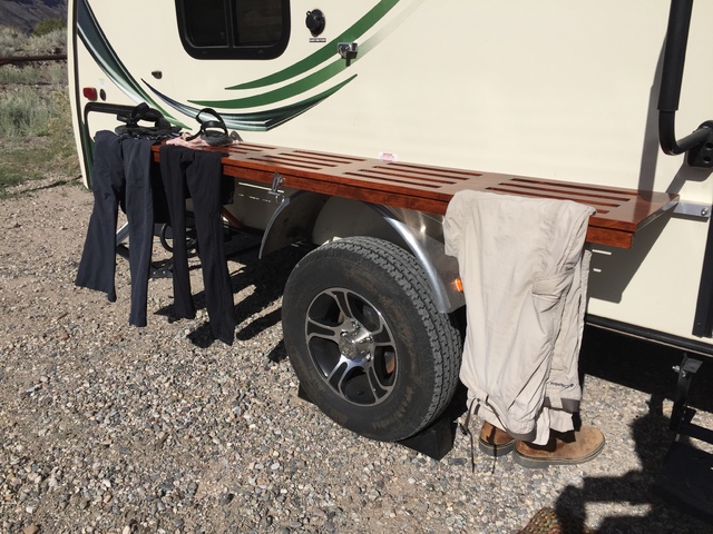
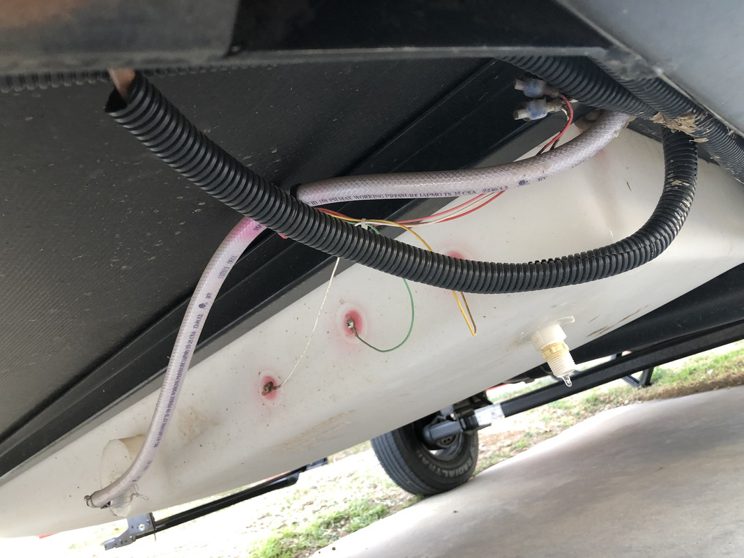
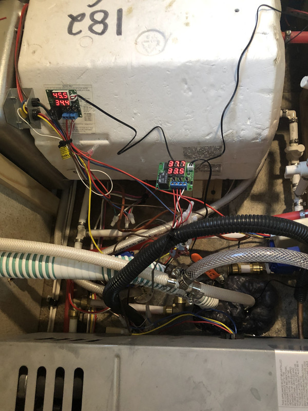
I have the recirc system up and going. I have tested some and it works. The placement of the thermostat sensor for a the recirc side is still ongoing. My first attempt was in a place too exposed and basically caused the water heater and pump to run continuously. I had my whole fresh water tank at 60 deg when freezing outside. No surprise then I am low on propane and it will be cold for several days and I don’t have time to test right now. So I wintrrezed the pod for now to focus on exposed pipes. The 182g has three water pipe exposures. Two are low point drains and I think I have ideas to insulate those as I can’t remove them. The third is the supply line that runs from the tank to inside the pod. It is about three fry long and totally exposed and is a definite problem. Scratching my head on that right now. Reroute maybe, insulate it triple? Not sure yet. That is definitely the place for the thermostat sensor.
The system runs from one switch. It is really a on-off-on switch called a dpdt with led indicators. When switched to red, the valve controlling whether cold water flows normally is closed. This also powers the thermostat that controls the two valves that allow hot water to recirc and return via the overflow line and ultimately the fresh water tank. I had some water spew from overflow so I had to reduce flow accordingly. I will post some pics. |
|
|
|
|
texman
Senior Member
Joined: 24 Jul 2014 Location: TeXas Online Status: Offline Posts: 446 |
Posted: 18 Feb 2019 at 6:07pm |
|
|
|
|
|
texman
Senior Member
Joined: 24 Jul 2014 Location: TeXas Online Status: Offline Posts: 446 |
Posted: 18 Feb 2019 at 6:11pm |
|
|
|
|
|
texman
Senior Member
Joined: 24 Jul 2014 Location: TeXas Online Status: Offline Posts: 446 |
Posted: 18 Feb 2019 at 6:12pm |
|
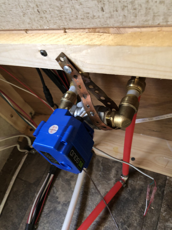
Rear mixing valve
|
|
|
|
|
texman
Senior Member
Joined: 24 Jul 2014 Location: TeXas Online Status: Offline Posts: 446 |
Posted: 18 Feb 2019 at 6:15pm |
|
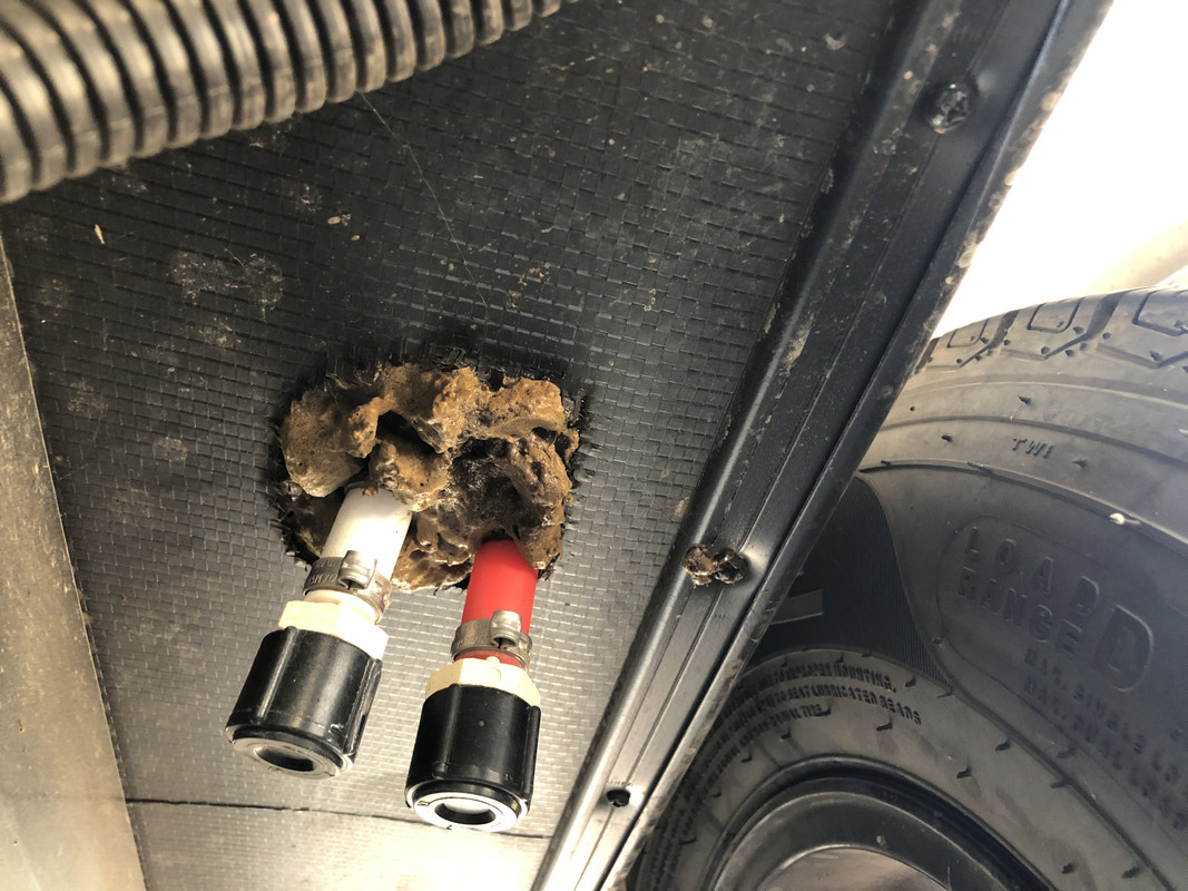
One of the low point drains. Other is almost identical
|
|
|
|
|
Post Reply
|
Page <1 2122232425 33> |
| Forum Jump | Forum Permissions You cannot post new topics in this forum You cannot reply to topics in this forum You cannot delete your posts in this forum You cannot edit your posts in this forum You cannot create polls in this forum You cannot vote in polls in this forum |


 Texman 182g Mods